


 Rebuilding Coleman® Two or Three Burner Stoves
Chapter Three: Reassembly
![]() My video on how to reassemble a 2 or 3 burner stove can be found here.
My video on how to reassemble a 2 or 3 burner stove can be found here.
3.1 Reassemble the valve. Gather your valve body with fuel tube, valve stem, valve stem nut and the packing retainer. If you removed the old packing during the cleaning process, have the new one out too.
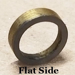
Start by sliding the packing retainer over the end of the valve stem. Notice that one side of the retainer is flat (Figure 1) while the other is beveled (Figure 2).
![]() Warning: The beveled side of the packing retainer must face the retainer stop on the valve stem.
Warning: The beveled side of the packing retainer must face the retainer stop on the valve stem.
 |
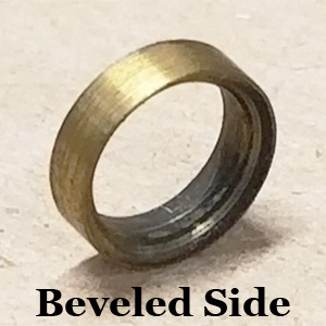 |
Figure 1 |
Figure 2 |
Slide the retainer on beveled side first so that it fits over the retainer stop ("C" clip). Follow this with the new valve stem packing (if replaced) and then the valve stem nut (Figure 3). If you didn’t replace the packing, just slide on the nut. Set your valve wheel on the back of the valve stem to temporarily hold these pieces together.
Hold the generator's tip cleaner rod in one hand and your partly assembled valve stem in the other. Insert the threaded end of the rod into the hole in the end of the valve stem and turn it clockwise. Once finger-tight, grasp the rod with pliers and hold it firmly (but not too tight) while turning the valve wheel clockwise (Figure 4). Once the rod spins inside the pressure you apply to the pliers, it is sufficiently tight.
 |
 |
Figure 3 |
Figure 4 |
Insert the sharp end of the tip cleaner rod into the valve and slowly move the valve stem towards the valve. When it reaches the valve body, turn it clockwise to seat it in the closed position. Slide the valve stem nut forward and turn it clockwise with your fingers until snug. Use a 1/2" wrench for two additional turns, then stop. We will tighten this later.
Pull the generator's coil an inch or so out of the generator tube. Feed the coil over the sharp end of the tip cleaner, followed by the tube (Figure 5). Be careful not to bend the tip. Slide them all the way to the valve and then turn the tube clockwise to fasten it (Figure 6). Use pliers or a wrench to tighten the generator tube.
 |
 |
Figure 5 |
Figure 6 |
![]() Thread lock is not required when installing the valve. I have been rebuilding lanterns and stoves for 20 years and have never needed it. Coleman sometimes used Loctite Red #262 or Gasoila Hard-set. You can use these, or Loctite Red #545 if you choose to, but never use pipe-dope or Teflon tape.
Thread lock is not required when installing the valve. I have been rebuilding lanterns and stoves for 20 years and have never needed it. Coleman sometimes used Loctite Red #262 or Gasoila Hard-set. You can use these, or Loctite Red #545 if you choose to, but never use pipe-dope or Teflon tape.
3.2 Install the Valve. Before installing the Valve, ensure that the tank is dry. If you still have water or alcohol inside, drain it out now.
Place the fuel tube into the tank and turn the valve clockwise to thread it in (Figure 7). At some point, it will start to get tight. Place the tank upside down in your bench vise with the squared top of the valve inside the jaws. Keeping the tank level as you rotate, gently turn it until the generator is overlooking the mounting tabs, perpendicular to the tank (Figure 8).
 |
 |
Figure 7 |
Figure 8 |
3.3 Tighten the valve stem nut. Place the valve wheel over the end of your valve stem and install the valve wheel screw. Turn the valve stem counterclockwise, then clockwise, and note the amount of resistance you feel.
With your 1/2” end wrench, slowly turn the valve stem nut clockwise while you turn the stem. Tighten the valve stem nut until you feel a noticeable drag. Once you can feel a good bit of resistance, give the nut another ¼ turn or so. Turn the valve stem fully clockwise to close the valve.
3.4 Install the check valve. If you left the check valve in your stove earlier, you can bypass this step.
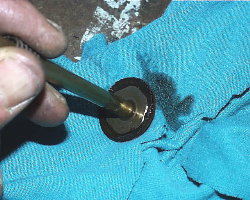
Figure 9 shows a new check valve, and that they come with an O-ring. If you are going to reuse your original check valve you may want to add an O-ring as it will seal the fount-to-valve connection much better. I went to Ace® Hardware and found a very close match. These O-rings are 1.5mm in width, I.D of 7mm and O.D. of 10mm and they are made of Viton.
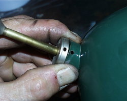
Take your new (or cleaned) check valve and remove the air stem. Tilt the tank on its end and drop the check valve down into the cylinder. Use a flathead screwdriver to turn it clockwise until snug.
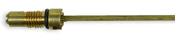 |
Figure 9 |
3.5 Install the air stem. Lower the bottom end of the air stem into the pump plunger hole, then turn it clockwise to install in the check valve. Finger-tight is fine.
3.6 Install the pump. Gather your pump assembly to include the pump clip. Ensure that all of the excess oil has been removed from in and on the pump (Figure 10).
Direct the bottom of the pump down into the cylinder, guiding the air stem into the hollow pump shaft (Figure 11). At the same time, start tucking the edges of the pump cup inside the cylinder. Ensure that the cup does not roll or catch an edge as you slide it down in the cylinder.
 |
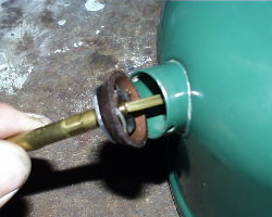 |
Figure 10 |
Figure 11 |
Press the pump down in the cylinder. Carefully fit the pump cap over the edge of the pump cylinder, ensuring that the “oil” hole is above the shaft and that the screw/clip holes in the pump cap are aligned with those in the tank (Figure 12). Press down evenly and firmly to align the holes.
With the pump cap properly aligned, install the pump clip to secure it. Insert one end in one hole, then use needle nose pliers to guide the other end into the second hole (Figure 13). It can be a tight fit so use caution, so you don't scratch anything.
Press the pump all the way to the bottom and rotate it clockwise until it stops.
 |
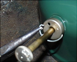 |
Figure 12 |
Figure 13 |
3.7 Install the fuel filler cap. Set your filler cap insert on the tank and then loosely install the filler cap over it. Before the cap gets tight, install the insert screw. Once you have it started, fully tighten down the filler cap and then take a screwdriver and tighten the insert screw. You will notice a space between the screw and the cap--this is normal.
3.8 Pressure test the tank. Fill the tank at least half-way with fuel, then install the filler cap and tighten it. Before starting, wipe off any fuel that may have spilled on the tank. Set it on a dry paper towel for testing. Keep your ears and eyes open for leaks.
![]() Note: These tests assume that your fuel filler cap/gasket is new, or in very good working condition.
Note: These tests assume that your fuel filler cap/gasket is new, or in very good working condition.
Place the valve wheel on the end of the valve stem and make sure the valve is fully clockwise. Rotate the pump handle one turn counterclockwise, grab the pump with your fingers and plug the hole with your thumb. Over-pressurize the stove by giving it 50+ pumps then rotate clockwise to close the pump.
Listen for air escaping and watch for wet spots. Areas to look closely at:
Valve-to-tank junction. Watch for the slightest amount of dampness or bubbles from around the threads. If you note a leak you probably need to turn the valve in the tank one more turn.
Valve stem nut. Look and feel for dampness along the bottom of the valve stem and nut. A leak here indicates that the stem packing has not been sufficiently tightened.
Seams and bottom of the tank. If you see ANY dampness around the seam or on the bottom of the tank, you need to find the source of the leak.
 Warning: ANY hole or crack in the tank renders the stove unsafe to use. Don't take the chance by trying to fix it with body putty or POR-15®. Get a replacement tank or set it on a shelf for display. DO NOT USE THE TANK.
3.9 Test the check valve. Turn the pump handle counterclockwise two full turns to open the check valve. Lightly rest your finger over the hole on the pump. Do not press down. What does the pump do?
If it does nothing, your check valve is working properly.
If it raises up, it is leaking. How fast it comes up tells you how bad the leak is. If it rises bottom to top in under 5 seconds, it is leaking too much to be safe.
Remove the pump and shoot some carburetor cleaner at the check valve to see if you can clean it better. If you cannot stop the leak, I recommend you remove the check valve.
If the pump rises slower than previously mentioned, you might be okay because the air stem is a positive stop (supplement) for the check valve.
You are the only one who can decide if your check valve is working well enough to be safe. The 5 second rule is only a guideline.
Your Tank is ready. Set it aside and we’ll put the case back together.
3.10 Install the drip tray. Slide the drip tray down inside the case, using caution not to scratch any of the paint. Ensure that the manifold holes in the tray line-up with the holes in the bottom of the case. Install the four or six screws that hold the drip tray in place (Figure 14).
 |
Figure 14 |
3.11 Install the Manifold. If you disassembled your manifold earlier to clean and/or paint it, put it back together and close the auxiliary burner valve(s). Lower it into the case, inserting the auxiliary burner control arm(s) into the side hole(s) so that it will fit. Align the studs on the manifold with the holes in the drip tray and press down. The manifold should sit flat on the drip tray.
Locate the nut and bolt that held the “U” portion of the manifold to the case and reinstall it (Figure 15). Snug down the nut but do not tighten it yet.
Set the case on its side and turn it so that you can see the bottom. Place one of your pal nuts on a 7/16” nut driver and carefully insert it into one of the access holes (Figure 16). When the nut reaches the stud on the manifold, turn clockwise and just snug them. Repeat for the other stud(s).
 |
 |
Figure 15 |
Figure 16 |
3.12 Align the generator and manifold. Set the case down flat and turn it so that you are viewing it from the front. Get your tank and install it in the case, just as if you were to use it.
The generator tip will probably not line-up with the hole in the manifold when you mount the tank the first time. Put the tank upside-down on your bench vise again and rotate the generator in the direction necessary for alignment and try again. The tank will sit flat on both tabs and the generator tip will be centered in the manifold hole when properly aligned.
Once you have set the generator alignment properly, tighten the bolt and screw at the “U” in the manifold. Then roll the stove on its back and tighten the two or three manifold pal nuts from the bottom.
3.13 Reassemble the burners. Locate your stove’s burner parts, which includes the burner caps, burner bowls, burner screws, the filler ring sets and possibly one baffle plate. The diameter of the master burner on most stoves is larger than the auxiliary burner(s). Lay these burner parts out in front of you and group them by size.
First set the burner bowls down on their respective boxes. If your stove has one, set the baffle plate down on the master burner bowl. Next come the filler ring sets, each consisting of four flat rings and three corrugated (Figure 17). The top and bottom rings are always flat; alternate between flat and corrugated (Figure 18).
 |
 |
Figure 17 |
Figure 18 |
Now set a burner cap on top of the first filler ring set, insert a burner screw in the center and thread it in. Tighten the burner screw to snug, then use your fingers to vertically align the cap and filler rings. Once the rings are properly “stacked” you can tighten down the screw (Figure 19). Repeat for the other burner(s).
 |
Figure 19 |
3.14 Prepare for lighting. Ensure your Filler Cap is tightened down.
![]() Caution! Ensure you have a fire extinguisher close-by before proceeding!
Caution! Ensure you have a fire extinguisher close-by before proceeding!
Twist the pump handle counterclockwise and pump the tank 20 times. Turn the pump handle clockwise to close. Hold a rag in front of the end of the generator to catch the fuel. Turn your valve wheel counterclockwise one full turn, then watch and listen. You should hear a gurgling sound inside the tank, followed shortly by a stream of fuel shooting out of the generator tip. With fuel coming out of the generator, turn the valve wheel fully clockwise to close the valve.
Check one more time for leaks. If you see a leak, fix it.
Install the tank on the case. Turn the lighting lever on the tank to the “Up to Light” position. Ensure that your auxiliary burner valve(s) is(are) closed.
3.15 Light the stove. Hold a lit match or lighter over the master burner and turn the valve wheel counterclockwise one half to one full turn until the burner ignites.
![]() It is very easy to flood a stove so keep the flame as small as possible.
It is very easy to flood a stove so keep the flame as small as possible.
The stove will initially burn with a large yellow flame (Figure 20) but will get smaller as the generator begins to get hot. Allow the stove to burn for a minute or so like this, then fully open the valve.
Rotate the lighting lever to the “Down to Burn” position and give the tank an additional 25 or so pump strokes to increase the flame intensity (Figure 21).
 |
 |
Figure 20 |
Figure 21 |
With the master burner burning, set your lit match or lighter over the top of an auxiliary burner and open the valve on the side of the stove. If you have a three-burner stove, light both auxiliary burners in the same manner.
Allow the stove to burn for a few minutes and continue to watch for leaks and drips. A small flame where the generator enters the valve, or where the generator enters the manifold indicates a leak that requires further tightening of the parts.
Close each auxiliary valve to shut off the auxiliary burner(s). Now turn the (main) valve fully clockwise to shut the stove off.
Your stove will not shut off immediately. Even with a closed valve, the fuel already in the generator can keep the burners lit for up to a minute.
![]() DO NOT PULL THE TANK FROM THE CASE WHILE ANY FLAME IS PRESENT!!!
DO NOT PULL THE TANK FROM THE CASE WHILE ANY FLAME IS PRESENT!!!
If you removed the legs or the towel rack or some other small piece from your stove, put it back together.
Congratulations! You've finished and have a "brand new" stove to use and enjoy.
 |
 |