


 Rebuilding Coleman® Two or Three Burner Stoves
Chapter One: Disassembly
 |
 |
1.1 Drain the old fuel. Pour the old fuel into an approved container for disposal. Use a length of clear tubing to siphon the fuel that won't pour out. You can find a local hazardous waste recycling facility by doing an internet search.
1.2 Disassemble the (3-Piece) fuel filler cap. This is the common filler cap with a panhead screw in the center. Reinstall the cap on your tank and tighten it down as much as you can with your fingers.
Note that there is a gap between the top of the cap and the bottom of the screw. Spray this junction with penetrating fluid and wipe away the excess. Allow it to sit for a few minutes.
Locate the medium-sized flat tip screwdriver that best fits the center screw in your filler cap. Place the blade in the slot, aligning the screwdriver squarely down on the center screw. Apply firm downward pressure and attempt to turn the screw counterclockwise. If it comes free, remove it and set it aside.
If it seems to slip as you turn the screw, the fuel filler cap is not tight enough. Re-tighten the cap with your fingers and try turning the screw again. You can also tap lightly on the handle of your screwdriver with a wrench or small hammer a few times.
If the screw will not come out after hand-tightening three or four times, you will need to use pliers. If you have nice paint that you don't want to scratch, wrap a rag around the filler cap and gently approach it with slip-joint pliers. Be very careful and don’t scratch the tank as the jaws turn. Be gentle on the squeeze but don’t allow them to slip either.
Once you have the screw out, loosen the filler cap and remove it. You should find the insert still sitting on your tank. Pull it off and set it aside.
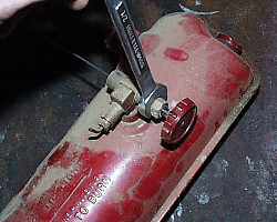
1.3 Remove the valve wheel. Hold the wheel firmly while you use a small flat tip screwdriver to loosen and remove the screw. Gently tap on the valve wheel to loosen it, then pull it from the valve stem.
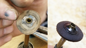
1.4 Remove the pump. Turn the tank so that you can see the pump and locate the pump clip, or pump screws on an older model. Use a small flat tip screwdriver to remove the screws or to pry away one side of the clip, then the other (Figure 1). Set the pump clip or screws aside.
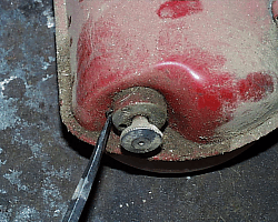 |
Figure 1 |
Firmly grab the pump handle and pull it out of the tank. If you find that the pump cap is "frozen" to the tank you can pry it free with your screwdriver. Once it comes free, inspect the condition of the leather pump cup. If it just dried out but appears to be intact, you can probably revive it. If the leather has rotted or if it has torn somewhere, replace it.
1.5 Disassemble the pump. Turn your pump upside down to see how the pump cup is being held on. You may see some variation of a hex nut, or a thin self-locking “push-on” nut (Figure 2). Also note the flat surfaces on the round pump shaft, near the bottom end. Use these flat areas to hold the pump with pliers or wrench.
If your pump is the style with a nut, use an adjustable wrench to turn it counterclockwise and remove. If it is the style with a push-on nut, place a small flat-tip screwdriver blade between the nut and the pump cup and carefully pry it off the end of the shaft. With the nut gone, remove the pump cup. Grab the outer edge of the backing plate with pliers and turn it counterclockwise to remove. You can now slide the return spring and pump cap off the pump. The disassembled pump is shown as Figure 3.
Note: If your pump is clean and in nice visual condition, you probably don't need to disassemble it unless you need to replace the pump cup.
 |
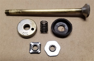 |
Figure 2 |
Figure 3 |
1.6 Remove the air stem. With the pump removed, you can see the air stem sticking out of the pump cylinder (Figure 4). Use pliers to turn it counterclockwise until loose, then remove.
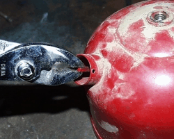 |
Figure 4 |
 Caution: You may want to bypass the next step! Extracting the check valve from your stove tank can be difficult and may not be necessary. Please review my section on check valves if you have any questions about removing it.
1.7 Test and/or extract the check valve. Again, you may not want to remove the check valve unless you need to. Here is a simple test that will give you an idea of how well your check valve is working:
Clean the outside of the pump cylinder well, the place your mouth around it (yuk!). First blow into the tank, and then try to pull air back out of it. If you can push air into the tank but you can't suck it back out, the check valve is probably working just fine. You will be testing it again during re-assembly so if you have a problem you can deal with it then.
If you need to extract the check valve, go here for guidance on how to do it.
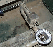
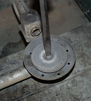
1.8 Remove the fuel valve. Turn the tank upside-down and place the squared top of the valve inside the jaws of your bench vise (Figure 5). Keep the tank level as you snug the vise down on the valve.
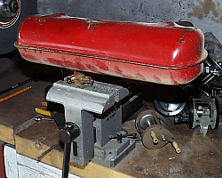 |
Figure 5 |
What you want to do is unscrew the tank from the valve. Grab the tank firmly with both hands and slowly turn it counterclockwise, ensuring that you stay level as you turn. Once it comes free, release the vice and then unscrew the valve from the tank by hand.
The squared top of the fuel valve is approximately a 1/2" fitting, and you can use a wrench to remove it if you don't have a bench vise.
With the fuel valve removed, set the tank aside.
1.9 Disassemble the fuel valve. Grab the valve wheel from your parts box and put it back on the end of the valve stem. Turn the valve wheel counterclockwise until it stops. Spray the valve stem with carburetor cleaner and use a small wire brush to clean the grease and dirt from the valve stem. Return the valve wheel to the fully clockwise position.
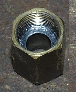
While holding the valve wheel closed, use a 1/2” end wrench to turn the valve stem nut counter-clockwise (). Do not allow the valve stem to turn when you do this. Continue turning the nut until the threads release from the valve body.
When the valve stem comes free as shown in Figure 7, pull it completely out of the valve. Don't bend the tip cleaner rod and be careful with the tip.
 |
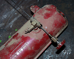 |
Figure 6 |
Figure 7 |
Next you want to remove the generator tube, or housing. There is usually a wrench fitting on this tube, near the point where it attaches to the valve. If your stove has a fitting, use the appropriate end wrench and turn the tube counterclockwise. If there is no fitting for a wrench, use a pair of pliers or vice grips to turn it (Figure 8).
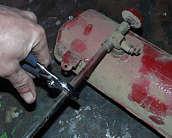 |
Figure 8 |
With the generator tube free from the valve, remove the generator coil from inside of the tube.
![]() Caution: The spring may be "locked" inside the tube due to carbon build-up. Exercise caution when removing it.
Caution: The spring may be "locked" inside the tube due to carbon build-up. Exercise caution when removing it.
On the other end of the generator tube you'll find the gas tip, and the gas tip protector. The "protector" is nothing more than a cover for the gas tip that holds it in place. Use the appropriate wrench to unscrew the gas tip protector. Once it comes free, the gas tip will either fall out or will stick to the inside of the tube or the protector.
1.10 Loosen the fuel tube. Hold the valve in your hand and use a wrench or pair of pliers to turn the fuel tube counterclockwise. You won't be removing the valve’s block & needle assembly, but you want to keep the fuel tube attached to protect the needle. Once the tube is loose, set the entire valve aside.
Warning: The next step will destroy the valve stem packing in your stove. If you don’t need to replace it, skip this step and leave the packing inside the nut.
![]() Note: Some model 425 stoves use a smaller valve stem packing than normal. Most of them use a smaller 3/16" packing, but some use the larger (standard) 1/4" version. Simply measure the outside diameter (OD) of the valve stem to find which one fits your stove.
Note: Some model 425 stoves use a smaller valve stem packing than normal. Most of them use a smaller 3/16" packing, but some use the larger (standard) 1/4" version. Simply measure the outside diameter (OD) of the valve stem to find which one fits your stove.
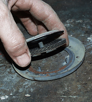
1.11 Remove the old valve stem packing. To remove the valve stem packing, we break it into little pieces. Look closely at the inside of your valve stem nut. You will see that the packing is pressed tightly against the threads (Figure 9). Set the nut down on your work bench with the large opening facing up. With a medium flat-tip screwdriver, angle the blade down inside to where the threads meet the old packing (Figure 10).
 |
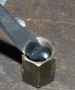 |
Figure 9 |
Figure 10 |
Press down on the screwdriver and “cut” into the packing. Slice it through to the threads, all the way to the bottom. With one cut into the packing, spin it around and do it from the opposite side. Continue until it breaks apart and you can completely remove it with a wire brush and/or a small screwdriver (Figure 11).
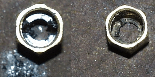 |
Figure 11 |
1.12 Separate the generator rod from the valve stem. Using a pair of pliers, grab the tip cleaner rod near the valve stem (Figure 12). Grip it firmly, then turn the valve wheel counterclockwise to unscrew the valve stem from the rod. Set these pieces aside.
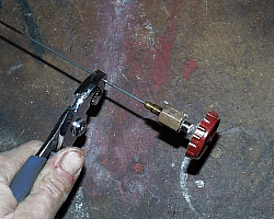 |
Figure 12 |
Congratulations, you've completed disassembly of your stove tank!
1.13 Remove the lid. There were several ways Coleman® attached their stove lids. Often times small metal tabs were riveted on to the sides of the lid, and they would fit into holes in the case. This held the lid in place yet allowed it to swing open or close. Other stoves used nuts and bolts to secure the lid to the case.
Once you identify the method of attachment for your stove, you should not have any difficulty figuring out the best way to remove it.
If your stove has a removable lid leg (towel rack) you can remove it and set it aside.
1.14 Remove the grate(s). Some grates, like on 425 models, sit loosely on the stove and are easily removed. Most other stove grates are attached to the case with clips.
If yours are loose, simply remove and set them aside. If they are attached to the stove, look closely at how they are attached. Most stoves will have a small strap around the grate ends that are held in place with a nut and bolt, as shown in Figure 13. Other stoves will have small push-in clips holding the grate, and they are kept there by small tabs that lock them to the case as shown in Figure 14.
If your stove has straps, just remove the nuts and bolts to release them. If it has the barbed clips, I recommend that you don't even try to remove them. They're a pain, and you'll probably damage one and/or the case getting them out.
To remove the grate from a stove with barbed clips, stand the grate upright and out of your way. Apply heat from a propane torch to one of the legs that are being held by the clip. Once the leg gets red-hot, remove the heat and bend the leg away from the clip until it becomes free.
1.15 Remove the manifold. The pipes you see inside your stove are collectively referred to as the manifold. At the back of the stove, locate the area where the “U” in the Manifold is secured to the case with a nut and screw (Figure 15). Use a flat tip screwdriver to turn the screw while you hold the nut with your fingers. Remove the nut & bolt and set them aside.
Turn the case on end and look at the underside where you'll see two (or three) large holes in the bottom (Figure 16). If you look into those holes you will see pal nuts that hold the manifold to the case (Figure 17). Use a 7/16" nut driver (or a socket with extension) to reach and remove them.
With the pal nuts removed, work the manifold back and forth to get it out. The control shaft for the auxiliary burner(s) is pretty long so take your time and be patient.
 |
 |
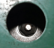 |
Figure 15 |
Figure 16 |
Figure 17 |
1.16 Disassemble the burners. The center of each burner has a large pan screw called the burner screw. Use a medium flat tip screwdriver to remove each burner screw as shown in Figure 18. If they will not turn, spray them with penetrating fluid and allow to sit for a few minutes. You can also tap on the screwdriver handle a few times with a small hammer.
![]() Note: Your stove has a master burner and one or two auxiliary burners. The master burner is always the nearest to the generator and the auxiliary burners will have an external valve to control them. They may be of different sizes.
Note: Your stove has a master burner and one or two auxiliary burners. The master burner is always the nearest to the generator and the auxiliary burners will have an external valve to control them. They may be of different sizes.
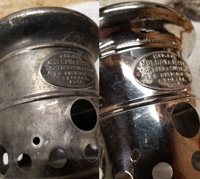
As you pull off the burners, notice how they were assembled. Each burner consists of a top burner cap, a set of "fillers" or burner rings, a burner bowl and a burner screw (Figure 19), and the master burner may also have a baffle plate that sits under the filler rings (Figure 20). Most burners will have three corrugated burner rings with four flat ones and working together they create the flame openings around the burner. Don't concern yourself with getting them all mixed up as you toss them into your parts box as they're easy to reassemble in the correct order.
 |
 |
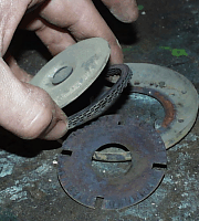 |
Figure 18 |
Figure 19 |
Figure 20 |
1.17 Remove the drip tray. If your stove has a drip tray, set the case down flat and turn it so you can see one of the ends. You will find two or three screws there, and they secure the drip tray (Figure 21). Remove the screws on one side, then the other. With the screws out, remove the drip tray and set it aside.
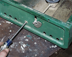 |
Figure 21 |
1.18 Remove the legs. If your stove has legs folded up inside the case, they are easily removed. Push in on the ends until they disengage, the pull them out.
Congratulations! You’ve finished tearing apart your stove! Go wash your nasty hands and get ready for part 2!