


 Rebuilding Coleman® Single Mantle Lanterns
Chapter One: Disassembly
If you are not mechanically inclined or are not comfortable working on fueled appliances, I encourage you to send your lantern or stove back to Coleman® for repair. Click here for more information.
Access to and use of this information constitutes your agreement with our Terms and Conditions. The material presented here is for informational purposes only.
![]() My video on how to disassemble a single mantle lantern can be found here.
My video on how to disassemble a single mantle lantern can be found here.
You may see photographs of double mantle lanterns during this lesson. Some of the parts are common to all lanterns, and even stoves. Rather than take another photo I simply used one photo for multiple lessons.
1.1 Drain the old fuel. Pour the old fuel into an approved container for disposal. You can find a local hazardous waste recycling facility with an internet search.
1.2 Remove the ball nut, bail, ventilator and globe. Unscrew the ball nut from the top of the lantern and remove it. Pull the ends of the bail outward and remove it. Lift off the ventilator and remove the globe. Set these parts aside.
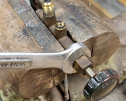
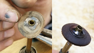
1.3 Remove the frame. Use a 7/16" end wrench to remove the frame nut at the bottom-center of the frame as shown in Figure 1. Gently lift the frame upward to pull it away from the lantern (Figure 2). Set the frame and frame nut aside.
 |
 |
Figure 1 |
Figure 2 |
If you are able to remove one of the washers under your frame, do it now and set it aside.
![]() If you are missing one or both washers, you should get try to get substitutes before finishing the lantern rebuild. The washer that goes around the center post is standard 1/4 ID" washer with an OD of approximately 9/16". The washer that goes under the generator is an odd size and you will need to visit the "specialty" bins in your local smaller hardware store to find it. The ID of this one is 3/8" and the OD is very close to 5/8". The reason for the odd size is a clearance issue. Look at the underside of the frame and you will see a channel running front to back. The washer sits inside this channel. If you use an incorrectly sized washer (larger OD) your frame will not sit on the lantern properly.
If you are missing one or both washers, you should get try to get substitutes before finishing the lantern rebuild. The washer that goes around the center post is standard 1/4 ID" washer with an OD of approximately 9/16". The washer that goes under the generator is an odd size and you will need to visit the "specialty" bins in your local smaller hardware store to find it. The ID of this one is 3/8" and the OD is very close to 5/8". The reason for the odd size is a clearance issue. Look at the underside of the frame and you will see a channel running front to back. The washer sits inside this channel. If you use an incorrectly sized washer (larger OD) your frame will not sit on the lantern properly.
1.4(a) Disassemble the frame (200 Series). Turn the frame upside-down to see where the burner tube enters the frame. Spray this area with penetrating fluid and allow it to soak for a few minutes.
With a 5/8” end wrench, loosen the nut holding the burner tube as shown in Figure 3. It can be difficult to get a wrench over this nut so use an adjustable wrench if necessary. Once you back the nut off one-half turn or so, try to remove the burner tube by turning it counterclockwise with your fingers.
If it isn't loose, spray the connection again with penetrating fluid and allow it to sit, then try again. If it still doesn't come out, wrap a cloth around the tube and gently grab it with channel lock or split joint pliers to free it. Remove the tube as shown in Figure 4.
 |
 |
Figure 3 |
Figure 4 |
Once you have the burner tube free, turn the frame over and remove the ventilator bracket, venturi and the U-tube. You might need to wiggle the U-tube a bit to free it from the venturi. Set these parts aside.
![]() Inspect the burner cap and screen. If the screen is missing or damaged you should replace the entire cap. If it looks good, you do not need to separate it from the tube.
Inspect the burner cap and screen. If the screen is missing or damaged you should replace the entire cap. If it looks good, you do not need to separate it from the tube.
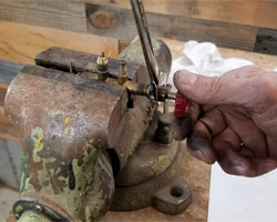
1.4(b) Disassemble the frame (242 Series). Spray the top connections of the frame with penetrating fluid and allow it to sit for 10 minutes or so. Hold the frame firmly and loosen the ventilator rod with a 7/16” end wrench. This may require holding the frame in a bench vise. Remove the ventilator rod and set it aside.
Wrap a thin rag around the Burner Cap and Screen and gently grasp it with a pair of channel lock or slip joint pliers. Being careful not to squeeze too hard, turn the burner cap counterclockwise to loosen it. Take your time and be gentle so that you don’t bend brass. Once it becomes free, turn by hand to remove. The burner tube may or may not come out with the burner cap, and that is fine. The Ventilator Rod and Burner Tube/Cap has been removed from the 242A frame in Figure 5.
![]() Inspect the burner cap and screen to ensure it is complete and undamaged. If the screen is missing or damaged you should replace the entire cap. If it looks good, you don't need to separate it from the tube.
Inspect the burner cap and screen to ensure it is complete and undamaged. If the screen is missing or damaged you should replace the entire cap. If it looks good, you don't need to separate it from the tube.
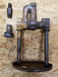 |
Figure 5 |
1.5 Remove the generator. Rotate the tip cleaner stem to the "UP" position. Use a 7/16” end wrench to turn the generator jamb nut counter-clockwise to loosen it as shown in Figure 6. Once is it loose, turn the jamb nut with your fingers until it spins freely.
Grasp the generator tube and lift it up about ½” to expose the bottom of the tip cleaner rod and eccentric block as in Figure 7. Pull the bottom of the rod away from the eccentric block and remove the generator and jamb nut. Set them aside.
You should now be able to remove the second washer, if your lantern has it.
 |
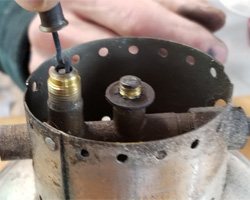 |
Figure 6 |
Figure 7 |
![]() Warning: If you have a painted lantern, use extreme caution during the next step so you don't chip or scratch the fount’s paint.
Warning: If you have a painted lantern, use extreme caution during the next step so you don't chip or scratch the fount’s paint.
1.6 Remove the frame rest. Turn the tip cleaner stem to a horizontal position and rotate the lantern so that the valve wheel is facing to your left. Look at the hole and slot at the front of the frame rest. You will notice that the slot is wider than the valve stem, and the hole is slightly larger than the valve stem nut.
Grab the frame rest with your right hand and gently push it forward towards the valve wheel. When it won’t go any farther, gently squeeze it to make it go slightly out-of-round (Figure 8). Once the frame rest bulges beyond the valve stem nut, lift the end of the frame rest until it clears the valve stem entirely and release your squeeze.
Gently lift and slide the frame rest to the right until you can remove it. Once off, set the frame rest aside. The valve is now exposed as shown in Figure 9.
 |
 |
Figure 8 |
Figure 9 |
1.7 Test the check valve. If you can, now is a good time to test the function of your check valve. This is possible if the pump is working and the fuel filler cap holds pressure.
Turn the pump fully counterclockwise and give the fount 20-25 pumps. Press the pump all the way down and let go of it. Rest a finger lightly over the hole in the pump handle and see what happens. If your fount is pressurized and nothing happens, your check valve is working properly. If the pump raises your finger upward the check valve is leaking.
If it lifts your finger very slowly, you can probably get away with not removing the check valve, because the air stem is a positive stop safety for you. However, if it pushes your finger up quickly, you need to clean or remove the check valve.
![]() Make a note of how your valve is positioned in the fount before continuing. This is called "clocking".
Make a note of how your valve is positioned in the fount before continuing. This is called "clocking".
Most 242 series lanterns manufactured before the mid-1940s were made with the pump to the left of the valve wheel and the filler cap to the right. Canadian 200 series lanterns were made the same way. Most 242 series lanterns made after the mid-40s, and all US-built 200 series lanterns, were made with the pump to the right of the valve.
1.8 Remove the valve. Use a small flat tip screwdriver to remove the center screw on the valve wheel and set it aside. Pull the valve wheel off the end of the valve. If the direction disc sticks to the inside of the wheel, slam it face-down on your bench once or twice to free it. Set the wheel and direction disc aside.
Turn the fount upside-down and place the valve body inside the jaws of your bench vise. You can place a cloth in the jaws to protect the valve if you wish to. Keep the bottom of the fount level as you snug down the vise.
Use caution as the fount is soft and easily bend and/or damaged by being careless. What you want to do is unscrew the fount from the valve. Grab the fount firmly in both hands and gently squeeze. Hold it close to your body and slowly rotate it counterclockwise, ensuring that it stays level as you turn it (Figure 10). Use the filler cap and pump to aid in turning as necessary.
Once it comes free, release the vice and then unscrew the valve by hand. When the threads are free, pull it out of the valve (Figure 11). Set the fount aside.
 |
 |
Figure 10 |
Figure 11 |
1.9 Remove the fuel & air tube. Hold the valve in your hand and turn the fuel & air tube counter-clockwise with a 5/16” end wrench as shown in Figure 12. When the threads are free, pull the tube away slowly so you don’t lose the metering rod and spring that are inside (Figure 13). Set the fuel & air tube aside.
 |
 |
Figure 12 |
Figure 13 |
1.10(a) Disassemble the valve (200 Series). Get the valve wheel from your parts box and place it back on the valve stem, then use it to turn the valve stem fully counterclockwise. Use a small wire brush and carburetor cleaner to remove the grease and dirt from the valve stem. Return the valve wheel to the fully clockwise position once the stem is clean.
While holding the valve wheel stationary, use a 1/2” end wrench and slowly turn the valve stem nut counterclockwise (Figure 14). Do not allow the valve stem to turn while you are doing this. Continue turning the nut until the threads release from the valve body. Now turn the valve wheel counter-clockwise and pull the valve stem out of the valve body (Figure 15).
 |
 |
Figure 14 |
Figure 15 |
Remove the valve wheel and slide the valve stem nut off the back side of the valve stem. When the nut comes off, locate the small brass valve stem packing retainer (Figure 16). It will probably be loose and obvious, but it may stick to the valve stem nut where it can later fall off. Set this ring aside along with the valve stem nut, valve wheel and the valve stem.
 |
Figure 16 |
The tip cleaner stem is still in the valve body and we are going to leave it there. It was not designed to be removed and will be destroyed if you try. Luckily, the graphite packing inside very rarely fails so we don’t need to remove them very often. We will make sure it is properly tightened when we put the lantern back together.
![]() If it does not spin 360 degrees or binds up during rotation, the tip cleaner stem or the eccentric block is damaged. Ensure you have new parts before pulling the tip cleaner stem.
If it does not spin 360 degrees or binds up during rotation, the tip cleaner stem or the eccentric block is damaged. Ensure you have new parts before pulling the tip cleaner stem.
1.10(b) Disassemble the valve (242 Series). Place the valve upside-down in your bench vise. Turn the valve wheel fully counterclockwise. Take a small wire brush and clean the grease and dirt from the valve stem. Return the valve wheel to the fully clockwise position.
While holding the valve wheel, use a 1/2” end wrench and slowly turn the valve stem nut counterclockwise (Figure 17). Do not allow the valve stem to turn while doing this. Continue turning the nut until it comes free from the valve body. Now turn the valve wheel counter-clockwise and remove the valve stem (Figure 18).
 |
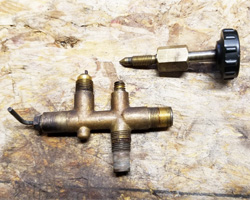 |
Figure 17 |
Figure 18 |
The tip cleaner stem is still in the valve body and we are going to leave it there. It was not designed to be removed and will be destroyed if you try. Luckily, the graphite packing inside very rarely fails so we don’t need to remove them very often. We will make sure it is properly tightened when we put the lantern back together.
![]() If it does not spin 360 degrees or binds up during rotation, the tip cleaner stem or the eccentric block is damaged. Ensure you have new parts before pulling the tip cleaner stem.
If it does not spin 360 degrees or binds up during rotation, the tip cleaner stem or the eccentric block is damaged. Ensure you have new parts before pulling the tip cleaner stem.
 Removing the valve stem packing on the 242-series lantern is a HUGE safety issue. Unless you know that your packing is bad, I recommend that you skip this step and leave your valve stem assembled. If it ends up that you need to replace the packing, you can easily remove the valve stem and do this step later.
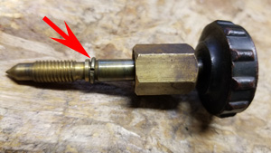
1.11 Disassemble the valve stem (242 Series only). Set your valve stem down on your workbench and locate the small retainer stop (C-clip) near the center of the valve stem (Figure 19). Spin the stop around so that you can see the ends of it. Using a small flat-tipped screwdriver, gently pry open one side, then the other. Continue to pry open until you can slide it off the end of the valve stem. With the retainer stop removed you can also remove the retainer (Figure 20) and then the valve stem nut. Set the retainer and stop aside.
 |
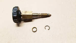 |
Figure 19 |
Figure 20 |
1.12 Remove the old valve stem packing.
To remove the valve stem packing we will need to break it into little pieces. Look closely at the inside of your valve stem nut. You will note that the packing is pressed tightly against the threads (Figure 21). Set the nut down on your work bench with the large opening facing up. With a medium flat-tip screwdriver, angle the blade down inside the nut to where the threads and the old packing meet (Figure 22).
 |
 |
Figure 21 |
Figure 22 |
Press down hard on the screwdriver to “cut” into the packing. Slice the packing through to the threads, all the way to the bottom. With one cut into the packing, spin it around and do it from the opposite side. Continue until the packing breaks apart and you can completely remove it (Figure 23).
The old packing must all be completely removed from the bottom end of the nut. Use a wire brush and carburetor cleaner to remove it. Set the valve stem nut aside.
 |
Figure 23 |
1.13 Remove the pump. Spin your fount around and locate the pump cap.
If your lantern has two small screws securing the pump cap, remove them with a small flat-tip screwdriver. If your lantern has a metal clip holding on the cap, use that small flat-tip screwdriver and carefully pry one end of the pump clip out of the hole in the cap. Firmly grasp the free end with needle-nose pliers and guide it away from the cap (Figure 24). It will be very tight so be careful not to scratch the finish on your pump cap or fount.
 |
Figure 24 |
Take some spray cleaner and wet the pump cap down. Allow it a minute or two to soak. Use a firm soft brush to remove the grease and oil from around the cap.
Grasp the pump handle and pull it up until you feel it reach the top. Now give it a few good upward tug to unseat the cap from the fount.
It may require a little work to get it off. If you are unable to unseat the cap after pulling up firmly on the pump, you might need to pry the cap off the fount. Place the blade of a small flat-tip screwdriver under the bottom edge of the cap and gently lift, working your way around the cap until it comes free. Be careful not to damage the finish on the fount. Set it aside.
1.14 Disassemble the pump. Turn your pump upside down to see how the pump cup is being held on. You may see some variation of a hex nut, or a thin self-locking “push-on” nut (Figure 25). Also note the flat surfaces on the round pump shaft, near the bottom end. Use these flat areas to hold the pump with pliers or wrench.
If your pump is the style with a nut, use an adjustable wrench to turn it counterclockwise and remove. If it is the style with a push-on nut, place a small flat-tip screwdriver blade between the nut and the pump cup and carefully pry it off the end of the shaft. With the nut removed, remove the pump cup. Grab the outer edge of the backing plate with pliers and turn it counterclockwise to remove. You can now slide the return spring and pump cap off the pump. The disassembled pump is shown as Figure 26.
 |
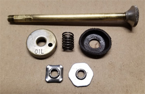 |
Figure 25 |
Figure 26 |
Inspect the condition of the leather pump cup. If it just dried out but appears to be intact, you can probably revive it. If the leather has rotted, or has torn somewhere, it needs to be replaced.
Warning: If you have a model 242 or 242A look for the hole in the pump that you would normally cover with your thumb. A pump without the hole indicates that the lantern has an old-style No Return Valve (NRV) style check valve. This type of check valve must be treated with special care. Please email info@oldtowncoleman.com if you have never worked with this check valve.
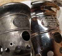
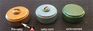
1.15 Remove the fuel filler cap. Unscrew the fuel filler cap from the fount. I ALWAYS recommend using a new replacement cap whenever possible.
If you have an original one-piece cap that color-matches your 200-series lantern, polish it with your fount and use it for display. When you use the lantern, install a replacement cap.
If you have an original three-piece cap that color-matches your 200-series lantern, polish it with your fount and use it for display. When you use the lantern, install a replacement cap.
If you have a 242-series lantern, there is not a replacement filler cap available for your lantern and you will need to replace the insert gasket.
1.16 Disassemble the (3-Piece) fuel filler cap. This is the common filler cap with a panhead screw in the center. Reinstall the cap on your lantern and tighten it down as much as you can with your fingers.
Note that there is a gap between the top of the cap and the bottom of the screw. Spray this junction with penetrating fluid and wipe away the excess. Allow it to sit for a few minutes.
Locate the flat tip screwdriver that best fits the center screw in your filler cap. Place the blade in the slot, aligning the screwdriver squarely down on the center screw. Apply firm downward pressure and attempt to turn the screw counterclockwise. If it comes free, remove it and set it aside.
If it seems to slip as you turn the screw, the fuel filler cap is not tight enough. Re-tighten the cap with your fingers and try turning the screw again. You can also tap lightly on the handle of your screwdriver with a wrench or small hammer a few times.
If the screw will not come out after hand-tightening three or four times, you will need to use pliers. Wrap a rag around the filler cap and gently approach it with slip-joint pliers. Be very careful and don’t scratch the fount as the jaws turn. Be gentle on the squeeze but don’t allow them to slip either.
Once you finally have the screw out, loosen the filler cap and remove it. You should find the insert still sitting on your lantern. Pull it off and set it aside.
1.17 Remove the air stem. With the pump removed from the fount you can see the air stem down inside the pump cylinder. Use needle-nose pliers to turn it counter-clockwise until loose (Figure 27). Use your fingers to continue turning, then remove. Set the air stem aside.
 |
Figure 27 |
1.18 Test and/or remove the check valve. As I stated previously, you do not want to remove the check valve unless you need to. If you were able to test it earlier and know that it is good, you are done.
If you were unable to test it, you can do a simple test now. Clean the outside of the pump cylinder well, the place your mouth around it (yuk!). Blow into the fount, then try to pull air out of it. If you can't pull air out, the check valve is probably working just fine. You will be testing it again during re-assembly so if you have a problem you can deal with it then.
The location of the check valve is shown in Figure 28. If you need to remove it please visit the page on how to do this.
 |
Figure 28 |
Congratulations! You’ve finished tearing apart your lantern!
 |