


 How Pressure Appliances Work
Part II: Making Gas
The previous chapter ended with pressurized fuel being delivered to the lantern's fuel valve via the fuel tube. Now we can pass fuel through the valve up to the burner where it is heated to generate gas vapor.
![]() It is very important to understand that pressure appliances DO NOT burn gasoline or kerosene—they burn the gaseous vapor of gasoline or kerosene.
It is very important to understand that pressure appliances DO NOT burn gasoline or kerosene—they burn the gaseous vapor of gasoline or kerosene.
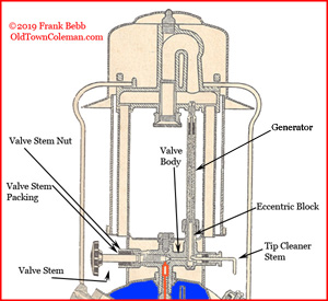
Figure 7
Figure 7 shows the upper half of our lantern, with the pressurized fuel (in red) sitting below the fuel valve stem. It shows the valve closed, meaning that the valve stem wheel has been turned fully clockwise, blocking fuel from passing into the valve.
When we turn the valve stem wheel counterclockwise, the valve stem pulls away from the valve body, allowing an amount fuel to pass through to the generator. The rate at which fuel is delivered depends on how far the valve is opened. Coleman® recommends that you open the valve "1/4 turn" to light many lanterns, which barely allows the fuel to flow.
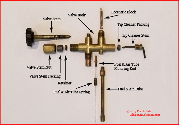
Before we move on, we need to discuss why the valve body doesn't leak. The photo to the right offers an "exploded" view of a lantern valve. The valve stem (left side) and the tip cleaner stem (right side) are both inserted into the hollow valve body, and both use compression fittings with graphite packings. This allows the valve stem and tip cleaner stem to turn freely without leaking fuel.
Note the shape of the tip cleaner stem. When it is inserted into the valve body, the end with the "dog-leg" fits into that slot at the bottom of the eccentric block. The eccentric is a device that converts the rotation of the tip cleaner stem to an up and down motion. So what goes up and down? Part of the generator does, which is where we'll go next.
![]() The generator is the heart of the lantern or stove because it generates a gaseous vapor from liquid fuel.
The generator is the heart of the lantern or stove because it generates a gaseous vapor from liquid fuel.
The generator is a hollow brass tube where our gasoline or kerosene is heated to point where it turns to vapor. The end of the generator, called the gas tip, has a very small hole that shoots the gas vapor into the lantern's burner. There is also a "filler" material, usually a spring and/or cardboard, used for heat transfer and to slow the fuel flowing through the generator. The last item is the jamb nut which compresses the bottom of the generator against the valve so it does not leak.
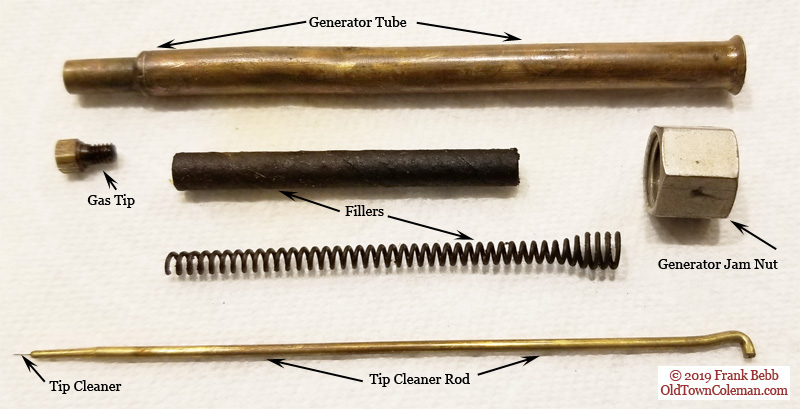
You can imagine how dirty this little gas tip gets after a few hours of intense heat and dirty fuel running through it. To clean the gas tip, we have a "tip" cleaner rod inside the generator. The tip cleaner rod has a needle on one end (the tip cleaner) that pokes through the gas tip when activated.
Older lanterns, like the 220/228 double-mantle or 200A single-mantle, have a tip cleaner stem that you rotate to clean the generator gas tip. Newer ones, like the 286/290/295 series lanterns, the tip cleaning function is built into the fuel valve. That is, when you turn the valve counterclockwise, the tip cleaner pokes the gas tip for you.
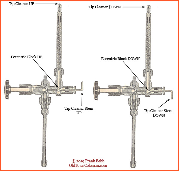
Figure 8
Figure 8 shows the relationship between the tip cleaner, the stem, and the eccentric block, in a vintage single-mantle lantern. To move the tip cleaner, we rotate the tip cleaner stem. As we rotate it, the eccentric block moves up and down which in turn moves the Tip Cleaner up and down. When it is up, the tip cleaner protrudes the gas tip to keep the small hole clean.
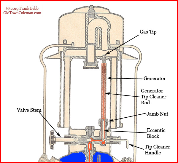
Figure 9
Now we can open the valve and allow fuel to flow up to our lantern burner and Figure 9 shows the path. With the valve stem turned counterclockwise, fuel enters the valve body. It will flow past the tip cleaner stem and eccentric block and up into the generator.
With a hot gaseous vapor exiting the gas tip of our generator, we will end the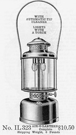 "Making Gas" portion of How a Lantern Works.
However, before we move on, we need to cover the fuel & air tube. The fuel & air tube is a magical invention that changed the way we light lamps, lanterns and stoves.
You'll remember that the primary function of the fuel tube is to deliver fuel to the fuel valve. Because a pressure appliance needs gas vapor to run properly, the obvious problem was how to get vapor from a cold lantern.
![]() Kerosene lanterns do not have fuel & air tubes.
Kerosene lanterns do not have fuel & air tubes.
One hundred-or-so years ago, Coleman® pressure lamps were considered to be torch lighting. The "torch" was actually a cloth swab shaped like a 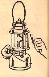 pitch fork that was dipped in alcohol and set ablaze to pre-heat the generator prior to lighting.
As time went on the size and/or shape of the generator changed to allow pre-heating with one or two stick matches, rather than the bulky torch. An old Q99 generator was shaped with a coil in the center which provided an obvious spot to apply the flame from your matches.
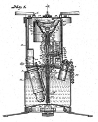
The next design improvement was the invention of the fuel &![]() air tube. As described in a 1920s US Patent filed by the Coleman Lantern and Stove Company, "The fuel tanks usually contain liquid under pressure, so there is an air space above the liquid. The air in the space becomes highly impregnated with the more volatile constituents of the fuel and makes a very good fuel in the gaseous state."
air tube. As described in a 1920s US Patent filed by the Coleman Lantern and Stove Company, "The fuel tanks usually contain liquid under pressure, so there is an air space above the liquid. The air in the space becomes highly impregnated with the more volatile constituents of the fuel and makes a very good fuel in the gaseous state."
During start-up, the fuel & air tube takes the (highly impregnated) air at the top of the fount and delivers it to the burner. When the lantern heats up and you open the valve, the fuel & air tube adjusts the fuel and air mixture to allow raw fuel to flow to the fuel valve and generator.
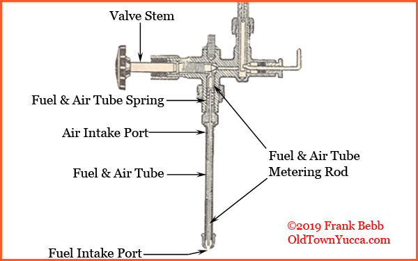
Figure 10
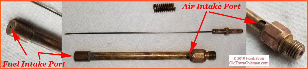
Figure 10 shows our fuel valve with the fuel & air tube. I have labeled the two intake ports on the fuel & air tube, one for air near the top and one for fuel at the bottom. This is consistent with what you just read in the patent filing and is important to consider as we discuss cold starts.
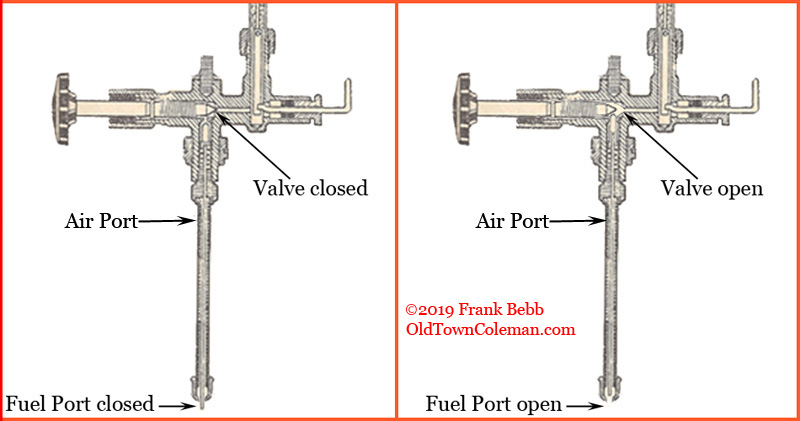
Figure 11
The tip of the valve stem comes to a point, which serves two purposes. First, it seats against the valve body when turned fully clockwise and seals it off. Secondly, it controls the fuel and air mixture by moving the metering rod up or down. This relationship is shown in Figure 11.
With the valve stem fully clockwise the fuel valve is closed, or off. The valve stem is holding the fuel & air metering rod down which effectively closes the fuel intake port at the bottom of the tube.
As the valve stem is turned counterclockwise to open, the metering rod underneath it will follow its conical shape and begin to rise. There is a small spring inside the fuel & air tube which helps move the rod upward. As the valve stem continues to open the metering rod will lift to its highest point and completely opens the fuel intake port at the bottom of the fuel & air tube.
The air intake port is always open; the metering rod only opens or closes the fuel intake port.
So when you "open valve 1/4 turn to light" you are moving the metering rod slightly upward, which slightly opens the fuel intake port. The air intake port is always open so the fuel/air mixture you're feeding to the burner has more air than fuel, which is desired for easy starting.
As you continue to open the valve, the metering rod lifts to the maximum height. This opens the fuel intake port and allows raw fuel to flow into the fuel valve and generator. This is the correct fuel/air relationship for normal operation.
Now we've covered how fuel gets from the fount to the generator, and how the fuel & air tube makes a cold lantern easy to start. Part III will continue with making fire, which will cause our Mantle(s) to illuminate.
![]() Part I: Creating and maintaining pressure
Part I: Creating and maintaining pressure
![]() Part III: Igniting the vapor to luminesce the mantle
Part III: Igniting the vapor to luminesce the mantle
![]() Part IV: Talking about stoves and burners
Part IV: Talking about stoves and burners