


 How Pressure Appliances Work
Part I: Under Pressure
Some lamps use a braided cloth to "wick" fuel up from a fuel tank while others use gravity to provide fuel to their burners. "Pressure" lamps, and other Coleman® appliances like lanterns, stoves irons, heaters and burners use pressure to deliver their fuel to where it needs to go, just as your car does.
Pressure is developed and maintained in the fuel reservoir, called the “fount” on a lamp or lantern or the tank on a stove or burner.
Figure 1 gives us a look inside a lantern fount, with the internal parts removed for clarity. Take note of the large diagonal cylinder in yellow. Near the bottom of this cylinder is a small tube that extends upward, almost reaching the top of the fount. That entire assembly is referred to as the pump cylinder and it is hollow. If you were to blow air into the large end, it would exit via the smaller tube inside the fount.
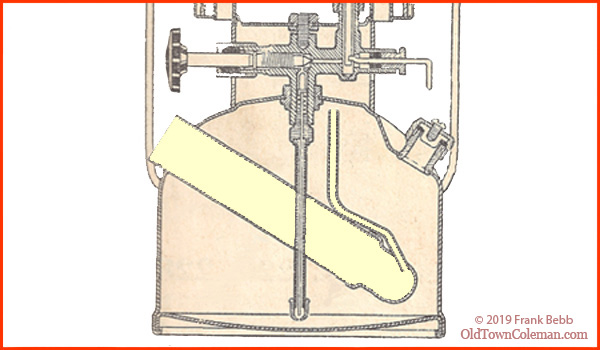
Figure 1
Now we can install the devices that go inside of the pump cylinder, which includes the pump, check valve and air stem as shown in Figure 2.
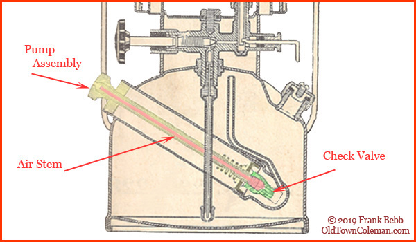
Figure 2
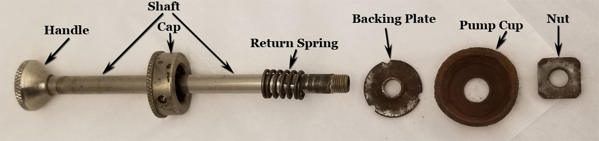
The pump is what we use to create pressure. It consists of a hollow tube with a handle, a cap used to fasten it to the lantern, a return spring to dampen the pumping motion, and a leather or plastic pump cup used to create a seal inside the pump cylinder. The pump cup is sandwiched between a backing plate and a nut to hold it secure.
The check valve threads into the fount and ensures that the air being pumped into the fount does not escape back through the pump cylinder. There is a small check ball at the bottom that allows air to flow in one direction only. Air can move down the pump cylinder into the fount, but it cannot flow back out of fount.
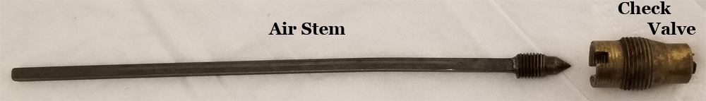
The air stem is a supplemental means of sealing air inside the fount. The pointed tip threads inside the check valve and acts as a plug. Turning the pump clockwise threads the air stem's tip deeper inside the check valve until it is completely blocked. Turning it counterclockwise retracts the pointed tip from the check valve and allows air to flow past it. The word “CLOSE” with an arrow is imprinted on the top of most Coleman® pump handles. What you “close” (or open) is the check valve, by rotating the air stem.
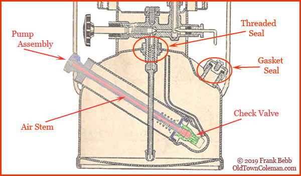
Figure 3
Before we pressurize the fount, we should discuss how to maintain the pressure we create. There are three holes in the fount that require an air-tight seal. The first is at the pump, and our check valve takes care of that one. The two circled areas of Figure 3 represent the two other holes in the fount.
The lantern's fuel valve enters the fount from the top and is threaded to provide an air-tight seal.
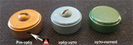
The third hole is where we pour our fuel into, and it is sealed via a heavy rubber gasket in the fuel filler cap.
With the fuel valve installed, the fuel filler cap tightened down and the check valve closed, our fount is air-tight.
When we want to use a lantern or stove, the first thing we do is turn the pump handle counterclockwise, place our thumb over the little hole in the handle and start pumping. Simple enough, but let's see what happens.
The top-right inset of Figure 4 shows a closed check valve, a result of the pump rotated fully clockwise (CLOSE). The bottom inset shows the air stem partially extracted, which was accomplished by twisting the pump counterclockwise and retracting the air stem from the check valve.
![]() The following illustrations show fuel as red and air as blue.
The following illustrations show fuel as red and air as blue.
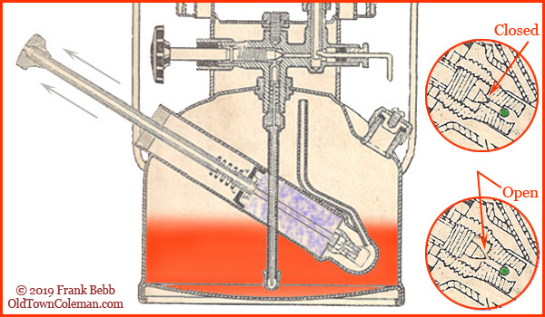
Figure 4
When we place our thumb over the hole and pull the pump back, a small vacuum is created below the pump cup. Air cannot be pulled out of the fount because of the check valve. As the pump cup moves up the cylinder, outside air is pulled over the pump cup to fill the vacuum. With the pump fully extracted, fresh air (shown in light blue) fills the area between the pump cup and check valve.
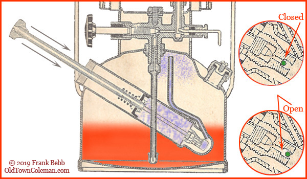
Figure 5
The downward movement of the pump pushes the fresh air down towards the check valve. The increasing pressure forces the check ball down, opening the check valve and allowing air to flow through the small inlet tube into the fount.
When the pump reaches the bottom and stops, pressure from inside the fount will act on the check ball and close the check valve. The next downward pump stroke will open the valve, and then it will close again.
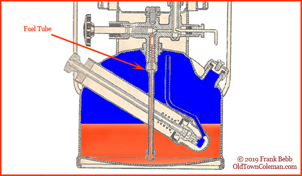
Figure 6
When we finish pressurizing the lantern, we return the pump to the bottom and rotate it clockwise to "Close". Again, this seats the air stem so that the check valve is double-locked. A fully pressurized lantern is shown in Figure 6.
Look at the fuel tube labeled in Figure 6. This device delivers fuel from the fount to the fuel valve. The center of the tube is colored red to represent pressure pushing the fuel up through the fuel tube and into the fuel valve.
The term “fuel tube” is a generic term as all pressure appliances have one, but not all of them are referred to as the fuel tube. Most pre-1930s gasoline lanterns, and all kerosene pressure lanterns, have a fuel tube that is simply a hollow tube which delivers fuel to the fuel valve. Gasoline appliances made after the mid-1920s came with a re-designed 3-piece unit that made them much easier to light, and we call it the "fuel and air tube". We will cover this device in the next chapter.
![]() Part II: Heating the fuel to create a gas vapor
Part II: Heating the fuel to create a gas vapor
![]() Part III: Igniting the vapor to luminesce the mantle
Part III: Igniting the vapor to luminesce the mantle
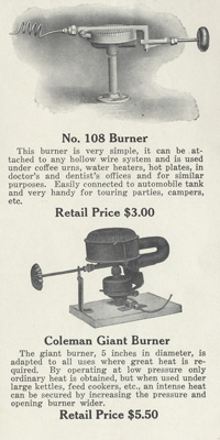
![]() Part IV: Talking about stoves and burners
Part IV: Talking about stoves and burners